Showing posts with label Electrical Qestion & Answers. Show all posts
Showing posts with label Electrical Qestion & Answers. Show all posts
03 January 2019
14 November 2018
117.Transistor as an amplifier
For a transistor to act as an amplifier, it should be properly biased. We will discuss the need for proper biasing in the next chapter. Here, let us focus how a transistor works as an amplifier.
Transistor Amplifier
A transistor acts as an amplifier by raising the strength of a weak signal. The DC bias voltage applied to the emitter base junction, makes it remain in forward biased condition. This forward bias is maintained regardless of the polarity of the signal. The below figure shows how a transistor looks like when connected as an amplifier.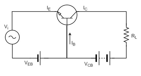
Example
Let there be a change of 0.1v in the input voltage being applied, which further produces a change of 1mA in the emitter current. This emitter current will obviously produce a change in collector current, which would also be 1mA.A load resistance of 5kΩ placed in the collector would produce a voltage of
5 kΩ × 1 mA = 5V
Hence it is observed that a change of 0.1v in the input gives a change of 5v in the output, which means the voltage level of the signal is amplified.
04 October 2018
116.Battery voltages
LEAD ACID BATTERY
· Generated voltage is 2
volts
· A lead-acid cell will gas freely
when fully charged but an alkaline cell gases throughout the charging period. The only indication of a fully
charged alkaline cell is when its voltage remains at a steady maximum value of
about 1.6-1.8 V.
· After a 10 hour discharge a lead-acid cell voltage will
have fallen to approximately 1.73 V
· The state of charge held by a lead-acid battery is
best indicated by a test on the electrolyte specific gravity (SG) by using a hydrometer or measuring the terminal voltage
when on load.
· A fully charged lead-acid cell has an SG of about
1.27-1.285 (often written as 1270-1285) which falls to about 1.1 (or 1100) when
fully discharged. the SG values quoted above for lead-acid cells are based on
an ambient temperature of 15°C. (Add 0.007
to reading for each 10°C above 15 °C
& Subtract 0.007
from reading for each 10°C below 15°C.)
NICKEL CADMIUM CELL
·
Generated
voltage is 1.2 volts
·
The state of charge of an alkaline battery cell cannot be determined from its SG value.
The electrolyte density does not change during charge/discharge cycles but
gradually falls during the lifetime of the battery.
·
New alkaline cells have an SG of around 1190.
When this reduces to about 1145 (which may take 5-10 years depending on the
duty cycle) the electrolyte must be completely renewed or the battery replaced.
Discharge of alkaline cells should be discontinued when the cell voltage has
fallen to about 1.1 V.
115.Faraday's laws of electro magnetic induction
Faraday's First Law:
Any change in the magnetic field of a coil of wire will cause an emf to be induced in the coil. This emf induced is called induced emf and if the conductor circuit is closed, the current will also circulate through the circuit and this current is called induced current.
Faraday's Second Law:
It states that the magnitude of emf induced in the coil is equal to the rate of change of flux that linkages with the coil. The flux linkage of the coil is the product of number of turns in the coil and flux associated with the coil.
114.440V eath fault alarm. Actions
First action is to check the trueness of the alarm. Usually there will be a test button which when pressed, resets the alarm and rechecks the condition of the earth fault.
If the ship is having IAS (Integrated Automation System), check on the computer in the list of events after which the alarm has activated. If IAS facility is not available, there is only one option of isolating each and every machinery in the 440 V circuit and check whether the earth fault indication returns back to normal. Isolation of all machinery, which operates on 440V, is not always possible. Certain critical equipment like steering gear and lubricating oil pumps cannot be isolated for when the ship is underway. However changeover can be done from running machinery to the standby one and thus the earth fault can be found
If the ship is having IAS (Integrated Automation System), check on the computer in the list of events after which the alarm has activated. If IAS facility is not available, there is only one option of isolating each and every machinery in the 440 V circuit and check whether the earth fault indication returns back to normal. Isolation of all machinery, which operates on 440V, is not always possible. Certain critical equipment like steering gear and lubricating oil pumps cannot be isolated for when the ship is underway. However changeover can be done from running machinery to the standby one and thus the earth fault can be found
113.Single phase Induction motor working
Construction of a single phase induction motor is similar to the construction of three phase induction motor
having squirrel cage rotor, except that the stator is wound for single
phase supply. Stator is also provided with a 'starting winding' which is
used only for starting purpose.
When the stator of a single phase motor is fed with single phase supply, it produces alternating flux in the stator winding. The alternating current flowing through stator winding causes induced current in the rotor bars (of the squirrel cage rotor ) according to Faraday's law of electromagnetic induction. This induced current in the rotor will also produce alternating flux. Even after both alternating fluxes are set up, the motor fails to start . However, if the rotor is given a initial start by external force in either direction, then motor accelerates to its final speed and keeps running with its rated speed
When the stator of a single phase motor is fed with single phase supply, it produces alternating flux in the stator winding. The alternating current flowing through stator winding causes induced current in the rotor bars (of the squirrel cage rotor ) according to Faraday's law of electromagnetic induction. This induced current in the rotor will also produce alternating flux. Even after both alternating fluxes are set up, the motor fails to start . However, if the rotor is given a initial start by external force in either direction, then motor accelerates to its final speed and keeps running with its rated speed
03 October 2018
112.Propeller shaft earthing
A difference in electrical potential between the hull and the propeller shaft will be generated due to the difference in materials and to the propeller being immersed in sea water.
In some cases, the difference in the electrical potential has caused spark erosion on the thrust and main bearings and journals of the crankshaft of the engine. In order to reduce the electrical potential between the crankshaft and the hull and thus prevent spark erosion, there must be installed a highly efficient shaft line earthing device.
The shaft line earthing device should be able to keep the electrical potential difference below 50 mV DC, and there must be installed a shaft to hull monitoring equipment with a mV-meter and with an output signal to the alarm system so that the potential and thus the correct function of the shaft line earthing device can be monitored.
Design description of the shaftline earthing device:
The shaft line earthing device consists of two silver slip rings, two arrangements for holding brushes including connecting cables and monitoring equipment with a mV meter and an output signal for alarm.

111.Fluorescent lamp working
- A fluorescent lamp basically consists of a long glass gas discharge tube. Its inner surface is coated with phosphorous and is filled with an inert gas, generally argon, with a trace of mercury.
- The tube is then finally sealed at low pressure with two filament electrodes each at its both ends.

The total electrical components for single tube light installation are
When the switch is ON, full voltage will come across the tube light through ballast and fluorescent lamp starter. No discharge happens initially i.e. no lumen output from the lamp.
At that full voltage first the glow discharge is established in the starter. This is because the electrodes gap in the neon bulb of starter is much lesser than that of inside the fluorescent lamp.
Then gas inside the starter gets ionized due to this full voltage and heats the bimetallic strip that is caused to be bent to connect to the fixed contact. Current starts flowing through the starter. Although the ionization potential of the neon is little bit more than that of the argon still due to small electrode gap high voltage gradient appears in the neon bulb and hence glow discharge is started first in starter.
As voltage gets reduced due to the current causing a voltage drop across the inductor, the strip cools and breaks away from the fixed contact. At that moment a large L di/dt voltage surge comes across the inductor at the time of breaking.
This high valued surge comes across the tube light electrodes and strike penning mixture (mixture argon gas and mercury vapor).
Gas discharge process continues and current gets path to flow through the tube light gas only due to low resistance as compared to resistance of starter.
The discharge of mercury atoms produces ultra violet radiation which in turn excites the phosphor powder coating to radiate visible light.
- Choke: it is electromagnetic ballast or electronic ballast.
- Starter: Small neon glow up lamp
- Switch
- Wires
110.Synchronous motor speed control
Synchronous motors
are constant speed motors. They run at the synchronous speed of the
supply. They are generally used for constant speed operation under no
load conditions such as to improve the power factor. Synchronous motors have fewer losses than induction motors at a given rating.
The speed of a synchronous motor is given by
N = 120 f / p
Where, f = supply frequency and p = number of poles
As you can see, the synchronous speed depends on the frequency of the supply and the number of poles of the rotor. Changing the number of poles is not easy, so we do not use that method. However, with the invention of solid-state devices, the frequency of the current fed to the synchronous motor can be varied. We can control the speed of the synchronous motor by changing the frequency of the supply to the motor.
109.Explain power factor
To understand power factor, we’ll first start with the definition of some basic terms:
KW is Working Power (also called Actual Power or Active Power or Real Power).It is the power that actually powers the equipment and performs useful work.
KVAR is Reactive Power. It is the power that magnetic equipment (transformer, motor and relay)
needs to produce the magnetizing flux.
KVA is Apparent Power. It is the “vectorial summation” of KVAR and KW
Power Factor (P.F.) is the ratio of Working Power to Apparent Power. = KW/KVA
How to improve power factor
1.Installing capacitors decreases the magnitude of reactive power (KVAR), thus increasing your power factor
2.By using synchronous condenser

107.Motor overhaul
1.
Checking the
insulation of the stator winding is very important before and after the
overhaul procedure.
2. Before dismantling any part of the motor or motor connection, marking of both motor housing and connection wires is very important. This will ensure that the boxing back procedure is smooth and there is no mismatch of parts. Also check the direction of the motor rotation before stopping the motor for overhauling.
3. Before overhauling the motor, pre-planning of removing and fixing back the motor safely in place must be discussed and implemented (depends on place where it’s fixed and also on the size of the motor) otherwise the load side (for e.g. Pump connected to motor) will be damaged by the motor shaft. The motor can be connected to the load as vertically coupled load and horizontally coupled load.
4. Dismantling can be done in two ways:
In place (On board ship, it is mostly applicable for very big vertically coupled motor to load)
Removing the motor from the
place by chain block
Remove the coupling and key
Keep the motor in place and
fix the nuts
Open the motor from top
(cooling fan side)
Take out the rotor by chain block, take
out the stator winding separately
Out place
Take out the motor from the place and
keep it in a horizontal position
Open the motor from any one side
If it’s a small motor take out the
rotor
If it’s a huge motor keep the rotor
inside and open the bearings using a good bearing puller
5. Removal of Bearing Housing Cover:
While removing the bearing
housing cover, note that some motors will be having inner bearing cover
tightened with nut bolts. Remove it carefully. In other constructions the
bearing housing cover is locked with bearing by a circle clip. Whenever
removing the housing cover on both sides (Driving End & Non Driving End)
make sure proper care is taken while handling.
6. Removal of Bearing or Coupling:
Use a suitable puller
(depends on the size of the bearing or coupling); mostly use the 3 arm puller
as it has a good pulling strength. First use the puller by barely applying any
pressure and try to take out the bearing or coupling, If it’s not coming out
even after enough load, use a pipe and extend the tightening spanner and try to
remove the bearing If the bearing is still stuck at the original position, heat
the bearing or coupling up to 100 deg. C while it’s locked with the puller and
apply little pressure If the bearing or coupling is not coming out with the
above tricks, the last method is to apply the load on puller through hydraulic
jack along with heating After opening the stator cover, thoroughly inspect the
inside condition of the stator. If there is little damage in rotor, repair it If
the insulation of the motor is less, clean the windings by an evaporative type
cleaner and give sometime to let it dry. Apply insulation coating and heat the
winding around 40 deg. C to 50 deg. C by means of powerful halogen lamps Clean
both side bearing housing covers, cooling fan, body of the motor and protection
cover of the motor with electro clean or suitable chemical
7. Insertion of bearings:
Clean the shaft on both
ends and heat the new bearing up to 70 deg. C to avoid tight insertion of the
bearing in the shaft. Do this for both sides. Wait for 20 minutes, let the
bearing cool down, and after that insert the bearing housing cover from one
side.
8. Box back the motor:
Before boxing up the motor,
do the insulation test again to compare with previous values. If the values are
on higher side, start boxing back, otherwise heat up the winding for some more
time with Halogen light. Box up to be done as per the markings Take up the
rotor with one side cover (If bearing locking nut were there in one of the
sides, prefer that to be the first to assemble) and push it inside the stator Lock
with one side nut bolts, slowly insert the other side cover, do the hammering
slowly by wooden hammer, insert and lock with nut and bolts, and the rotor will
now apply load on the bearing Gently tighten the bolts using opposite
tightening method. Insert the cooling fan and protection cover, and once again
verify the tightness of the bolt Fix in place the motor as per the marking and
give the connections accordingly. Try out and check the Amperage. Compare with
rated amperage and before overhaul amperage.
Note:
Check the direction of rotation after overhauling. If it indicates opposite
direction, it means the connection done is wrong105.Synchronous motor working
The synchronous motor and induction
motor
are the most widely used types of AC motor. The difference between the two
types is that the synchronous motor rotates in exact synchronism with the line
frequency. The
stator is wound for the similar number of poles as that of rotor, and fed with
three phase AC supply. The 3 phase AC supply produces rotating
magnetic field
in stator. The rotor winding is fed with DC supply which magnetizes the rotor.
Consider a two pole synchronous machine as shown in figure below.

- Now, the stator poles
are revolving with
synchronous speed (lets say clockwise). If the rotor position is such
that, N pole of the rotor is near the N pole of the stator (as shown in
first schematic of above figure), then the poles of the stator and rotor
will repel each other, and the torque produced will be anticlockwise.
- The stator poles are
rotating with synchronous speed, and they rotate around very fast and
interchange their position. But at this very soon, rotor can not rotate
with the same angle (due to inertia), and the next position will be likely
the second schematic in above figure. In this case, poles of the stator
will attract the poles of rotor, and the torque produced will be
clockwise.
- Hence, the rotor will
undergo to a rapidly reversing torque, and the motor will not start.
But, if the rotor is rotated
upto the synchronous speed of the stator by means of an external force (in the
direction of revolving field of the stator), and the
rotor field is excited near the synchronous speed, the poles of stator will
keep attracting the opposite poles of the rotor (as the rotor is also, now,
rotating with it and the position of the poles will be similar throughout the
cycle). Now, the rotor will undergo unidirectional torque. The opposite poles
of the stator and rotor will get locked with each other, and the rotor will
rotate at the synchronous speed.
It
is used in governors & in e/r crane
104.What will happen if we connect a 60 Hz appliance to 50 Hz supply
If we were to connect 60 Hz motor to a 50Hz supply then Motor
would work, but it will run at a lower speed. This would simply mean that
the work a motor is doing e.g driving a pump will be reduced and the pump will
run at a lower speed. This will eventually have an effect on systems where flow rate is important. Apart from running slow, motor will draw
more current than what it is designed for and as a result will cause
overheating of motor, which may eventually cause fire or a burn out of motor.
To avoid that overheating problem it is important to reduce the voltage. Always take into consideration the Voltage/Frequency ratio. Voltage/frequency ratio is always constant for e.g. 440/60 HZ = 7.33, Now taking 7.33 as constant and we have to connect a motor with a frequency of 50Hz the voltage should now kept at:- Voltage/50=7.33, This would mean , Voltage = 50*7.33=366.5 Volts.
102.Flapper nozzle
It is a transducer which converts varying mechanical input signal into varying air output signal.

When mechanical input is low , the gap between flapper and nozzle increases. as a result output decreases.

Air is fed to the nozzle at constant pressure via an orifice. Air leaks to atmosphere via nozzle is depend on the gap between nozzle and flapper.
When mechanical input is higher, it will push flapper against the spring thus gap between flapper and nozzle reduces and output pressure will increase(As amount of air leak between flapper and nozzle decreases)
When mechanical input is low , the gap between flapper and nozzle increases. as a result output decreases.
101.Transformer working
A transformer is a device that transfers electrical energy from one circuit to another by
electromagnetic induction (mutual induction). It is most often used to step up
or step down voltage
TRANSFORMER COMPONENTS
The principle parts of a transformer and their functions are --
• The core, which provides a path for the magnetic lines of flux.
• The primary winding, which receives power from the AC power source.
• The secondary winding, which receives power from the primary winding and
delivers it to the load.
• The enclosure, which protects the above components from dirt, moisture, and
mechanical damage.

The transformer circuit in shows basic transformer action. The primary winding is connected to a 60 hertz AC source. The magnetic field (flux) expands and collapses about the primary winding. The expanding and contracting magnetic field around the primary winding cuts the secondary winding and induces an EMF into the winding.
When a circuit is completed between the secondary winding and a load, this voltage causes current to flow. The voltage may be stepped up or down depending on the number of turns of conductor in the primary and secondary windings.
100.Ward-Leonard System

Ward Leonard method of speed control is used for controlling the speed of a DC motor.
Speed control of D.C. motor can be obtained by varying the applied voltage to the armature. Ward Leonard system of speed control is based on this principle.
In this method M is the main D.C. motor whose speed is to be controlled, and G is a separately excited D.C generator. The generator G is driven by a 3 phase induction motor
The combination of ac driving motor and the dc generator is called the motor generator set.
The output voltage of dc generator is control by varying the excitation. The output voltage is then fed to dc motor to control the speed.
99.DC motor speed control
1.Speed control of shunt motor
(a)Flux control method - By decreasing the flux, speed can be increased. Flux is controlled with the help of a rheostat.
(b)Armature control method - The voltage across the armature is adjusted by a variable rheostat.
(c)Voltage control method (Ward leonard system)
2.Speed control of series motor
(a)Flux control method
(b)Variable resistor method